 Dielectric Radomes
|
Maximum Protection Minimum Transmission Loss |
|
As required by sophisticated electrical performance requirements, impedance matching circuit elements are inserted into the dielectric flanges to reduce scattering loss. The superior performance and advantages of DSF Radome technology are evident in the worldwide Defense Satellite Communications System (DSCS, WGS, MET, GBS, MILSTAR, SBIRS, NOAA, NASA), weather radar, telemetry, radar, air surveillance radar and satcom communications.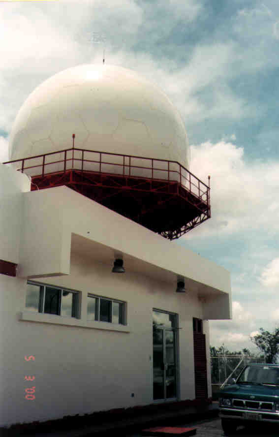 Antennas for Communications (AFC)
high technology radome capability combines the expertise of materials science, geodesic domes, prefabricated structures and electromagnetics. AFC manufactures six types of dielectric radomes. TM, SL, 2L, SFC, CLS and THS. The six technology types identify themselves primarily by the radome wall construction. In each case, the dielectric panel edges are reinforced into flanges for adjacent panel assembly. The panel flanges form a framework commonly called a Dielectric Space Frame (DSF) radome. Depending on radome wall structure, the adjacent panel flange framework may also serve as environmental load bearing beams or struts. Each panel is a molded one piece unit without bonds or seam lines. When assembled to the other panels, the panel array forms a truncated spherical surface. Individual panels may be doubly curved or flat yielding a faceted geodesic, stealth or spherical smooth appearance.
Antennas for Communications (AFC)
high technology radome capability combines the expertise of materials science, geodesic domes, prefabricated structures and electromagnetics. AFC manufactures six types of dielectric radomes. TM, SL, 2L, SFC, CLS and THS. The six technology types identify themselves primarily by the radome wall construction. In each case, the dielectric panel edges are reinforced into flanges for adjacent panel assembly. The panel flanges form a framework commonly called a Dielectric Space Frame (DSF) radome. Depending on radome wall structure, the adjacent panel flange framework may also serve as environmental load bearing beams or struts. Each panel is a molded one piece unit without bonds or seam lines. When assembled to the other panels, the panel array forms a truncated spherical surface. Individual panels may be doubly curved or flat yielding a faceted geodesic, stealth or spherical smooth appearance.
| The six DSF radome types are: |
|
| Maximum Environmental Protection | Minimum Transmission Loss |
|
|
 |
AFC engineers have developed a family of off-the-shelf COTS mold and tooling sets to manufacture radomes based on a range of required radome diameters. A set of radomes within a given range of radii have identical panel count, panel shape and overall geometric layout. Individual panel size and the flange angles, which are radius dependent, differ to accommodate the radome's overall shape factors. Spherical truncation is also radome specific, and is accommodated by sub panels unique to each requirement.
Radome accessories customize a radome to suit particular requirements. Accessories may include lightning protection, obstruction lights, ventilation, base collar, personnel door, indoor lights and power kits, hydrophobic coating and impedance matching. AFC has combined its extensive 30-year experience in composite material manufacturing with its RF electromagnetic experience to produce the dielectric radome. Dielectric radomes combine strength and weather resistance with minimal effect on microwave and radar frequency signals. |
Monolithic Segments
 AFC's TM, SL, SFC, CLS and THS dielectric radomes are constructed of flat or curved panel segments which combine a composite material window with a dielectric frame in one monolithic piece. DSF radome panel frameworks are interior to the radome so there is nothing to trap water in puddles or to launch ice adhesion. The only metal parts are stainless steel nuts and bolts holding the panel segments together. There are no metal components on the outside of the radome to corrode in hash environments or to discolor or stain radome panels. Without corrosion oxide induced diode mixers, DSF radomes are virtually intermodulation product free in the presence of modern multi-carrier communication systems and radar. The only exterior maintenance required is an occasional washing to remove dirt. No air pressure is required to support the radome. The six radome technologies are very rigid structures. In contrast to older thin membrane metal space frame radomes, there is no audible flutter, microphonics or "oil canning." Panels may be molded into spherical doubly curved or flat surface shaped panel units. For flat DSF panels, such as used in geodesic or Stealth radomes, the entire exterior surface of the radome is covered with TEDLAR or gelcoat. Tedlar or gelcoat are unique long-lasting materials with a proven weather resistant 25 year lifetime. An optional hydrophobic coating may be applied to the radome surface. This hydrophobic coating causes water to bead and run off in rivulets instead of sheeting. Hydrophobicity also serves to help anti-ice protection for the radome and reduces rain related transmission loss.
Low Transmission Loss
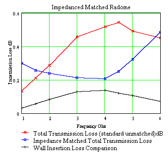
Radome transmission loss is composed of two major loss contributions. The first and usually the smallest contribution is the ordinary insertion loss of a microwave signal passing through the radome wall. The second and largest contribution is the scattering loss off the radome panel framework blocking the antenna aperture. Scattering loss is typically 4 to 100 times larger than the wall insertion loss. The use of a dielectric space frame greatly reduces the scattering loss associated with metal frames. This reduces the transmission loss, beam distortion and boresight error caused by a metal frame blockage. Use of a dielectric frame also eliminates the Faraday cage effect which inhibits the use of metal space frame radomes at lower frequencies. Every DSF radome exhibits the RF property that the total transmission loss, scattering plus wall insertion loss, approaches zero dB at low frequencies (as opposed to metal space frame radomes, whose loss increases without limit). This property is important for L-band radar and UHF/VHF radar or emergency radio communications contained within the radome.
Virtually Invisible and Impedance Matching
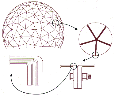
 The dielectric radome geometry is divided into several large sections. To eliminate the possibility of coherent scattering from panel framework blocking the antenna aperture, the sections are divided into random sizes of various shaped segments. Combining the sections produces a quasi-random or pseudo-randomly segmented radome, which minimizes coherent microwave scattering.
Scattering loss is greatly reduced in a radome by a process known as impedance matching. The reactance of the radome framework is removed by embedding electrical circuits within the framework. The electrical circuits impedance match, "tune out", the reactance of the radome framework over a design frequency band to reduce the scattering loss and the phase distortion along with its associated boresight shift and sidelobe perturbation. The use of stainless steel hardware with a dielectric space frame avoids any dissimilar metal contact, which can produce intermodulation distortion. |
Simple Installation
AFC dielectric space frame radome panels can be quickly assembled using normal hand tools. They can be assembled around existing antenna equipment or assembled and then lifted and set over the antenna equipment.
AFC can provide installation crews for a turnkey project or supervisors for customer installation. Because air pressure is not required to support the radome, several lower panels can be easily removed to permit large pieces of equipment or vehicles to be added or removed.
AFC has the in-house tooling capabilities and computer aided design techniques to quickly and economically produce custom dielectric radomes to meet any radome requirements.
| Composite Wall | PRETENSIONED LAMINATE, SANDWICH, CLS or THS |
| Radome Geometry | SPHERICAL, GEODESIC or STEALTH |
| Exterior Surface | TEDLAR � OR GELCOAT OPTIONAL SUPER-HYDROPHOBIC COATING, HYDROLAM 2000 |
| Air Pressure | NONE REQUIRED |
| Maintenance | ROUTINE CLEANING |
| Design Life | 25 YEARS (1.9 General Buckling Safety Factor) |
| Equatorial Diameter | Base Diameter | Radome Height | Center Height | Number of Panels |
||||
| meters | feet | meters | feet | meters | feet | meters | feet | |
| 0.9 | 3.0 | 0.9 | 3.0 | 0.9 | 2.9 | 0.4 | 1.4 | 1 |
| 1.8 | 6.0 | 1.8 | 6.0 | 2.1 | 7.0 | 1.2 | 4.0 | 1 |
| 2.3 | 7.5 | 2.3 | 7.5 | 3.0 | 10.0 | 1.5 | 5.0 | 4 |
| 2.6 | 8.4 | 2.6 | 8.4 | 2.6 | 8.5 | 1.3 | 4.3 | 4 |
| 2.9 | 9.6 | 2.9 | 9.6 | 2.8 | 9.2 | 1.3 | 4.4 | 4 |
| 3.7 | 12 | 2.7 | 8.9 | 3.0 | 10.0 | 1.2 | 4.0 | 7 |
| 5.5 | 18.0 | 3.9 | 12.7 | 4.7 | 15.4 | 1.9 | 6.4 | 13 |
| 6.2 | 20.3 | 4.4 | 14.4 | 5.2 | 17.1 | 2.1 | 6.9 | 40 |
| 6.7 | 22.0 | 5.6 | 18.4 | 5.2 | 17.0 | 1.8 | 6.0 | 22 |
| 7.3 | 24.0 | 5.7 | 18.8 | 5.8 | 19.2 | 2.2 | 7.2 | 36 |
| 8.0 | 26.4 | 6.5 | 21.4 | 6.4 | 21.0 | 2.4 | 8.0 | 55 |
| 9.5 | 31.0 | 6.6 | 21.8 | 7.8 | 25.7 | 3.1 | 10.2 | 75 |
| 9.8 | 32.0 | 7.1 | 23.3 | 8.1 | 26.7 | 3.2 | 10.6 | 55 |
| 10.7 | 35 | 8.3 | 27.3 | 8.7 | 28.5 | 3.3 | 11.0 | 106 |
| 11.1 | 36.5 | 8.3 | 27.3 | 9.2 | 30.3 | 3.7 | 12.0 | 106 |
| 12.6 | 41.4 | 8.8 | 28.7 | 10.9 | 35.6 | 4.5 | 14.9 | 160 |
| 12.9 | 42.2 | 9.1 | 29.7 | 11.0 | 36.0 | 4.5 | 14.9 | 111 |
| 14.9 | 48.8 | 11.4 | 37.3 | 12.2 | 40.2 | 4.8 | 15.9 | 275 |
| 15.8 | 52.0 | 12.1 | 39.7 | 13.0 | 42.8 | 5.1 | 16.8 | 275 |
| 17.2 | 56.3 | 12.2 | 39.9 | 14.6 | 47.8 | 12.2 | 39.9 | 285 |
| 18.6 | 61.0 | 14.7 | 48.2 | 15.0 | 49.2 | 5.7 | 18.7 | 410 |
| 20.7 | 68.0 | 16.2 | 53.1 | 16.8 | 55.2 | 6.5 | 21.2 | 425 |
| 21.5 | 70.5 | 17.3 | 56.8 | 17.1 | 56.1 | 6.4 | 20.9 | 425 |
| 23.0 | 75.5 | 19.3 | 63.2 | 17.8 | 58.4 | 6.3 | 20.7 | 425 |
| 24.4 | 80.0 | 18.5 | 60.8 | 20.1 | 65.8 | 7.9 | 25.8 | 600 |
| 28.3 | 93.0 | 19.6 | 64.1 | 24.4 | 80.2 | 10.3 | 33.7 | 840 |
| 29.6 | 97.1 | 23.7 | 77.7 | 23.7 | 77.7 | 8.9 | 21.3 | 840 |
| 33.5 | 110.0 | 23.0 | 75.5 | 28.9 | 94.8 | 12.4 | 39.8 | 1100 |
| Other custom sizes available. These radomes are available as standard dielectric or as impedance matched dielectric radomes. |
||||||||
AFC manufactures, markets and sells worldwide satellite dish antennas, radomes, antenna feeds, microwave and waveguide components and ultra low loss waveguide transmission line Tallguide �. Our customers serve the broadcast, communications, radar, weather and cable industry, defense, government, and government agencies worldwide. AFC's quality control manufacturing standards are certified under ISO 9001 : 2015.
Top of PageReturn to Radome Network Home Page
Telephone (352) 687-4121 Fax (352) 687-1203 E-mail sales@afcsat.com
Tallguide is a Registered Trademark of Antennas for Communications
Tedlar is a Registered Trademark of Dupont.
Copyright � 1997 - 2020 Antennas for Communications