
Solid Laminate and Sandwich
|
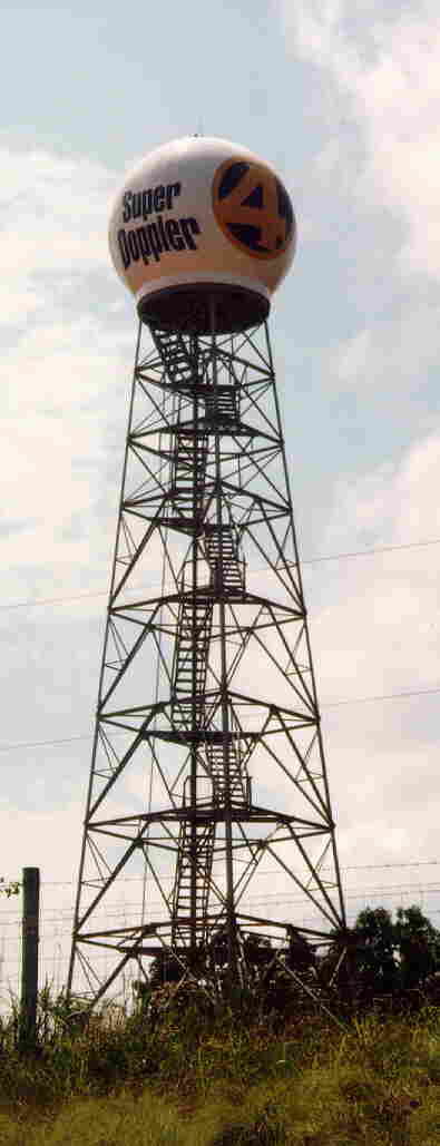
| 18 ft. (5.5m) diameter radome covering C-band Doppler weather radar. |
Radomes serve as protective shelters with window like properties that make the radome transparent to radar and communications signals. For demanding radar and communications systems, radomes safeguard against environmental design loads, such as wind, blowing sand, snow, ice, rain, ultra violet sun light, fungus and corrosion. AFC's 5.5 meter (18 foot) diameter radome is composed of 12 panels, which when assembled, forms a truncated spheroid. This radome is easy to assemble and to install in just a few hours. Typical 5.5-meter radome applications are general radar, weather radar, weather satellite, telemetry and satellite communications. The radome may be fabricated with a solid laminate or 3-layer sandwich wall.
Improving signal quality, radomes help tracking systems by removing random and often large dynamic wind forces. In the absence of wind pressure, undersized pedestals may be used to reduce antenna cost. Significantly increasing operational reliability and lifetime under extreme weathering conditions --- high winds, snow, ice and very cold temperatures --- radomes provide a benign environment for the enclosed equipment.
Along with environmental sheltering properties, radomes are subject to electromagnetic requirements. Transmission loss must remain low. At the same time, the radome noise temperature contribution must not significantly alter receiver sensitivity. Since most antennas move their pointing to almost any direction, the radome engineer must juggle competing electromagnetic and environmental loading conditions over the entire radome surface. Opposing performance objectives are the substance of an optimized radome design.
Optimized Radome
Radome transmission loss is composed of wall insertion loss and scattering loss off the radome panel flange framework blocking the antenna aperture. Not commonly known to most engineers, radome scattering loss is usually 4 to 100 times larger than the ordinary radome wall insertion loss. One method of reducing scattering loss off the panel flange framework is to introduce impedance matching techniques. Often impedance matching is employed to decrease radome scattering loss over some particular frequency band. Inductive tuning elements are used to "tune out" the capacitive reactance of the dielectric panel flanges. With the scattering loss near zero over the impedance matching bandwidth, transmission loss approaches the ideal wall insertion loss. Generally, a radome operational frequency band occurs where the wall insertion loss is very low. One problem with a solid laminate wall is that its insertion loss increases with frequency. At such high frequencies (C-band and above), a 3-layer sandwich wall significantly reduces wall insertion loss over a solid laminate. In addition, this sandwich construction frequency matching technique provides excellent thermal insulation along with minimal transmission loss. From an RF point of view, the 3-layer sandwich wall behaves as a low pass filter with cut-off frequency dependent on wall design dimensions. General practice is to place the cut-off frequency above the highest signal frequency component.
Eliminating Water Accumulation
After exposure to sunlight and the environment, microscopic damage is caused to standard radome surfaces. While not a structural problem, rain will tend to collect on the exterior surface and run off in sheets; significantly increasing wet insertion loss and system noise temperature. Such negative rain induced effects often occur when system performance mandates perfection. To help reduce the problems associated with microscopic surface damage, AFC has pioneered hydrophobic surface coatings. In stead of rain sheeting, a hydrophobic surface causes the radome to remain dryer, water to bead and run off in rivulets. With the radome surface effectively dryer, substantial improvements in wet transmission loss and noise temperature result in a superior performing radome. At the same time, hydrophobicity helps prevent ice from sticking to the radome surface.
Accessories
Radome accessories customize a radome to suit particular requirements. Typical accessories are listed below.
| Item | Specification
|
Accessories |
| Radome Type | Solid laminate | 3-layer sandwich |
| Outside Diameter | 5.5 meter (18 ft.) | Indoor lights and power kit |
| Inside Clearance Diameter | 5.38 meter (17.66 ft.) | Personnel hatch |
| Height | 4.7 meter (15.4 ft.) | Base collar to raise height |
| Base Outside Diameter |
3.9 meter (12.7 ft.) | Lightning protection |
| Base Clearance Diameter |
3.67 meter (12.04 ft.) | Aircraft warning lights |
| Number of Panels | 12 plus small top cap | Passive or forced ventilation |
| Wind Speed | Gust to 250 km/Hr (155 mph) | Severe wind speed to 322 km/Hr (200 mph) |
| Surface | White gelcoat | Hydrophobic coating |
| Temperature Range |
-45 to +70o C | Environmental control system |
| Frequency Range | Solid laminate frequency to 6.5 Ghz with increasing transmission loss above 4 Ghz | Sandwich frequency to 18 Ghz |
| Transmission Loss | See transmission loss graph example | Impedance matching |
| Transmission Loss for 5.5 m (18 ft.) Diameter Radome |
Radome Outline Drawing |
 |
 |
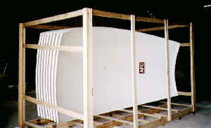
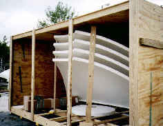
| Freight Preparation | |
 |
 |
AFC manufactures, markets and sells worldwide satellite dish antennas, conical horn antennas, radomes, antenna feeds, microwave and waveguide components, ultra low loss waveguide transmission line Tallguide �, and shelters. Our customers serve the broadcast, communications, radar, weather and cable industry, defense, government, and government agencies worldwide.
For additional information related to AFC's radome product line and technology, please refer to Dielectric Space Frame Radome Data Sheet and Radome Capabilities Brochure. Radome thermal insulation properties may be found in AFC's Application Note on Radome Thermal Insulation. The importance of radome surface hydrophobicity is discussed in Hydrophobic Coating Data Sheet. For large radomes, the Advantages of Dielectric Space Frame over Metal Space Frame Radomes are listed in detail.
A complete Internet WWW AFC document site index may be found in Antennas for Communications (AFC) Home Page Document Summary List.
Top of PageReturn to Radome Network Home Page
Telephone (352) 687-4121 Fax (352) 687-1203 Email sales@afcsat.com
Tallguide is a Registered Trademark of Antennas for Communications
Copyright � 1998 - 2002 Antennas for Communications