
Radome Transmission Loss
|
- Introduction
- Radome Geometry and Framework Shadowing
- Transmission Loss and Framework Electronic Signature
- Radome Framework Design Shape
- Radome Framework Impedance Matching,
- Radome Noise Temperature and Antenna System dG/T Degradation
- Antenna Pattern Degradation
- Stealth Radome Technology for Dual Pol Polarimetric Radar
- Compliance of Satellite Earth Station Antenna Patterns
- Radome Design Considerations for Satellite Earth Stations
-
Table of Contents
 Introduction
Radomes are composed of panels, which when assembled form a truncated spherical shell to protect the enclosed antenna from the environment. Each radome panel is surrounded by a flange perimeter enabling adjacent panel assembly. After assembly, the panel flange perimeter members form a framework characteristic of the panel shapes. Both the radome shell wall and panel framework are in the path of the shielded antenna. Radome transmission loss is the sum of the ordinary insertion loss of the antenna (radar) signal passing through the radome wall plus the scattering loss off the radome panel framework blocking (shadowing) the antenna aperture. From an antenna point of view, just as the antenna feed assembly, feed support struts or cassegrain subreflector block the antenna aperture, in the same fashion so does the radome framework that shadows the antenna aperture. While radome wall insertion loss is typically less than 0.1 dB, surprisingly, the scattering loss off the framework is 4 to 100 times larger than the wall insertion loss. Therefore, one must take into account the radome panel framework scattering loss in order to understand radome performance for protected antennas or radar.
In general, a larger scattering loss is encountered for a longer length framework shadowing the antenna aperture. For example, if the framework shadowing length is twice another radome, so is the radome scattering loss (transmission loss). What happens to this scattered energy is that it spreads out into the antenna sidelobes. The antenna pattern is corrupted by the scattering loss. Since sidelobes have small energy, the larger the radome scattering loss, the larger the effect on antenna sidelobes. The precise details of where this energy goes is dependent on the shadow length and radome transmission loss, the electronic signature of the framework and the positions and orientations of the framework members shadowing the reflector. For the most part, the scattered energy is directed into the far out sidelobes where the antenna sidelobe pattern is very weak. Here the antenna sidelobes may be affected from framework scattering by 6 to 12 dB. In contrast, where the antenna pattern is strong, the first several sidelobes are affected by only 1 dB.
This result should not surprise you. Antenna engineers have long since learned to orient feed support struts at 45-degree angles relative to the principle horizontal, vertical planes. Then when azimuth and elevation antennas patterns are measured, these measurement pattern cuts do not show the effects of feed support strut scattering. Nevertheless, the antenna pattern is still degraded by scattering from the feed support struts, but mostly in the not measured 45-degree pattern directions.![]() Radome Geometry and Framework Shadowing
Radome Geometry and Framework Shadowing
| Radome diameters 6.7m (22ft). | |
 |
|
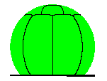
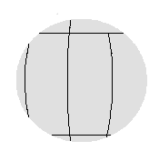
| Figure 1. Orange peel radome Geometry. | Figure 2. Quasi-random radome geometry. |
Consider a perfect radome (truncated sphere) without any panels. If we cut the radome vertically in half, we now have 2 panels and one framework seam member. As the radome protected antenna scans in azimuth, the framework shadows the antenna aperture starting from one edge, continuing over the antenna and then passing out the other side. The framework blockage length depends on the antenna scan angle and may vary from 0 up to the antenna diameter length when the framework member just bisects the reflector diameter.
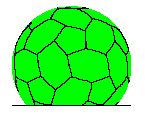
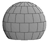
With actual radomes, framework shadowing is more complicated and depends on the radome geometry. Radome geometry is a term used to describe how the truncated sphere is separated into panel shapes. The mathematical process is known as tessellating the sphere. From a practical point of view, the radome must be packaged for shipment anywhere worldwide. What this means is that the maximum panel size must conform to standard shipping sizes. Taking into account shipping size constraints, two common radome geometry types for small radomes are the symmetric orange peel and quasi-random geometry shown in Figures 1 and 2 respectively. Quasi-random geometry radomes may have triangular, hexagonal or pentagonal panel shapes. A geodesic radome using triangular panels is an alternate implementation of the quasi-random radome geometry.
| Orange Peel | Quasi-random |
| |
|
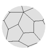
Figure 3. Radome framework shadow pictures for 6.7m (22ft) diameter radome with orange peel shadow (left) and quasi-random shadow (right). Antenna diameter is 4.3m (14ft). | |
Considering the radome geometry of Figures 1 and 2, what we see is that the framework shadow on the reflector surface is a complicated geometry problem dependent on the radome diameter, panel size, the antenna diameter and antenna scan angle. Figure 3 shows the radome framework shadows for both an orange peel and quasi-random 6.7m (22ft) diameter radome geometry protecting a 4.3m (14ft) diameter reflector antenna. To keep scattering loss low, normal practice is to use large radome panels. Therefore as the radome diameter gets smaller, the radome is manufactured from fewer panels with orange peel geometry.
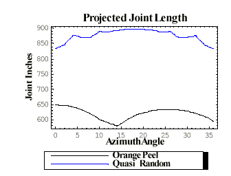 |
| Figure 4. Radome framework shadow length comparison for the orange peel and quasi-random 6.7m (22ft) diameter radome shown in Figure 1,2 and 3 above. |
On the other hand, one can purposely make the panels smaller where the framework shadowing would mimic the quasi-random nature of the radome (compare Figure 1, 2 and 3). Such a quasi-random radome with smaller panels would have a larger transmission loss due to the longer length of framework shadow members. Figure 4 graphically shows, as a function of azimuth scan angle, the extra shadow length for the quasi-random shadow compared to the orange peel shadow. Under such circumstances, the quasi-random shadow contributes 44 percent more blockage than the symmetric orange peel geometry radome. At the same time, we wish to point that there are good reasons for manufacturing smaller quasi-random radomes that contain more panels. AFC manufactures both 6m and 7m diameter quasi-random radomes called Stealth (STEALTH �). Stealth technology introduces unprecedented performance ideal for dual-polarized weather radar applications called polarimetric radar.
Note to reader: The extra shadow length problem associated with the quasi-random geometry is only a property of smaller diameter radomes where the radome panel size, antenna diameter and radome diameter have similar dimensions. For larger radomes, 8m (26ft) diameter and above, panel sizes are small relative to the antenna diameter. Here, the shadow length geometry differences becomes insignificant. We will see later that the for large radomes, the quasi-random geometry is superior and fundamental to achieving enhanced RF performance.
The framework electronic signature may be measured in an anechoic chamber (Figure 5) or calculated using Method of Moments electromagnetic simulation techniques. w*IFR measurements yield two complex numbers (amplitude and phase); one where the electric field polarization is oriented parallel to the framework; and the second when the electric field polarization is perpendicular.
Electronic signature w*IFR product amplitude is a measure of the effective electronic shadow width. Its value depends on:
When structural requirements make w large enough to exceed RF electromagnetic specification limits, two approaches are available to reduce transmission loss and electromagnetic degradation. The first method appeals to the design shape of the framework member. The second method appeals to a process known as impedance matching where the framework electronic signature w*IFR is reduced in value. Both methods are described below.
W.V.T Rusch, A.F. Kay and other investigators have shown that the framework scattering loss is approximately:
![]() Transmission Loss and Framework Electronic Signature
Transmission Loss and Framework Electronic Signature![]()
the framework shadow, w is the framework width, A is the antenna aperture area and IFR is the framework Induced Field Ratio. The w*IFR product is known as the framework electronic signature.
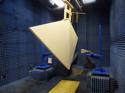
Figure 5. AFC anechoic chamber electronic signature and
panel insertion loss verification measurements.
Further, the framework width w has structural properties consistent with the maximum rated radome wind speed specification. To enhance RF performance, a balancing act takes place between a stronger structure with heavy-duty sized members (making w larger) and RF performance. This RF optimization process often determines that radomes are designed with structural safety factors appropriate for a lifetime of service. It is for this reason that AFC has defined radome structural safety by a criterion based on the geometric deformation of the radome shell, which leads to a catastrophic failure wind speed. We refer the reader to the AFC’s Radome Structural Analysis web page.
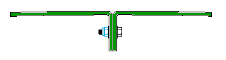
There are 2 flange framework forms common to the radome industry. The first type is called a perpendicular joint. The second type is called a parallel lap joint. Figures 6 and 7 picture both flange framework forms.
![]() Radome Framework Design Shape
Radome Framework Design Shape

| |
| Figure 6. Perpendicular joint's framework fastener hardware is internal to the radome. |
Figure 7. Parallel lap joint framework has fastener hardware external to the radome. |
 |
|
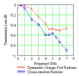
Figure 8. Transmission loss comparison for the 6.7m (22ft) diameter symmetric orange peel and quasi-random geometry radome. |
A radome transmission loss (scattering loss) comparison for the symmetric orange peel and quasi-random small 7.7m (22ft) radomes are shown in Figure 8. To help with the contrast, the perpendicular joint is used with the orange peel geometry radome and the parallel lap joint with the quasi random geometry radome. Figure 8 shows that the transmission loss and framework electronic signatures w*IFR increase from 0 at low frequencies to some maximum value dependent on the detailed design and dielectric joint properties. Clearly, the framework electronic signature w*IFR has fine structure that contributes to the complex nature of the transmission loss curves.
![]() Radome Framework Impedance Matching
Radome Framework Impedance Matching
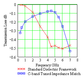 |
| Figure 9. Reducing radome transmission loss by impedance matching radome framework tuned for C-band. |
Clearly for a metal space frame radome, impedance matching is impossible. With a metal space frame radome, there is no approach for improving the framework electronic signature.
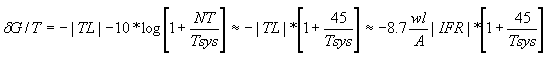
Radome noise temperature is the sum of the power absorption in the radome wall, noise reflection off the radome wall and noise scattering off the radome panel framework. In a similar process to radome transmission loss, noise from the warm earth scatters off the radome framework into the antenna feed system with a magnitude several times greater than the other two mechanisms. Noise temperature NT and dG/T is therefore proportional to radome transmission loss or electronic signature w*IFR as shown in the equation below, where Tsys is the antenna system noise temperature before the radome is installed.
![]() Radome Noise Temperature and Antenna System dG/T Degradation
Radome Noise Temperature and Antenna System dG/T Degradation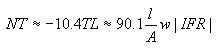
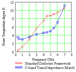 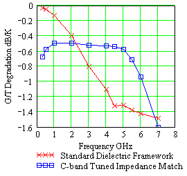 | |
| Figure 10. Radome noise temperature comparison between standard and impedance matched framework radome. | Figure 11. Antenna system dG/T degradation for impedance matched and standard radome. |
Antenna Pattern Degradation
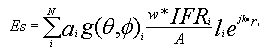
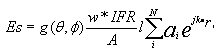
How the framework shadow members scatter energy and disturb the antenna pattern is a complex function of radome geometry, panel shape, framework orientation with angular rotation, framework length and electromagnetic signature properties as well as antenna polarization. Referring to the 2D shadow projection example, Figure 3, the framework shadow forms line segment members. Labeling ith framework member of length li, the total shadow length l (from the transmission loss equation above) is the sum of all the member lengths l = S li within the shadow. We note that the 2D shadow framework members actually refer to the framework members positioned on the geodesic or spherical radome surface. As such, framework members each have an element pattern that scatter energy into the sidelobes in preferred directions according to their length, orientation and electronic signature. By keeping track of the summation of all the framework member element patterns on the radome surface shadowing the antenna, one has a linear phased array antenna. Each element of the scattering phased array has an element gain given by electronic signature complex number w*IFR, which has amplitude and phase, along with numerical values associated with framework rotational angle and polarization. This geometrically complicated linear phased array scattering antenna is characterized by its electric field, Es with scatter pattern proportional to |Es|2. Adding the scattering phased array pattern to the antenna pattern electric field, Ea, we arrive at the total radome-enclosed antenna pattern, |Et|2, where Et is given by:
Et = Ea + Es
Antenna engineers view the scattering array pattern |Es|2 as degradation and therefore seek radome solutions where the scattering phased array pattern and radome transmission loss are very small. Over the main beam and first several antenna sidelobes, where the antenna power is strong, |Ea| > |Es| and radome scattering has little affect on the total pattern. In contrast for the far out sidelobes, where the antenna pattern is very weak, |Es| > |Ea| and the total radome-enclosed sidelobe level pattern is limited by the scatter pattern |Et|2 @ |Es|2. In between values, where that antenna sidelobe level and scatter pattern have equal amplitude, |Ea| = |Es| and the total radome-enclosed pattern |Et|2 is modified by +/- 6 dB.
By proper choice of the antenna aperture field pattern, ai, sum or monopulse difference pattern, the radome enclosed antenna may also be explored for boresight error, beamwidth error, axial ratio degradation, differential gain and phase as well as transmission loss and noise temperature.
For large radomes, where numerous framework members shadow the antenna aperture, quasi-random shadow blockage provides superior performance over the symmetric radome counterpart. When the radome geometry shadow pattern is symmetric, as with large orange peel radomes, the scatter pattern equation, above, may simplified by bringing the framework element pattern, framework electronic signature and framework member length outside the summation sign:
| Quasi-random | Symmetric Orange Peel |
 |
 |
 |
 |
 | |
| Figure 12. Scattering pattern for 10.7m (35ft) diameter radome with quasi-random and symmetric orange peel geometry. Note the grating lobes for the symmetric radome. Antenna is the ASR-9 radar operating in S-band. | |
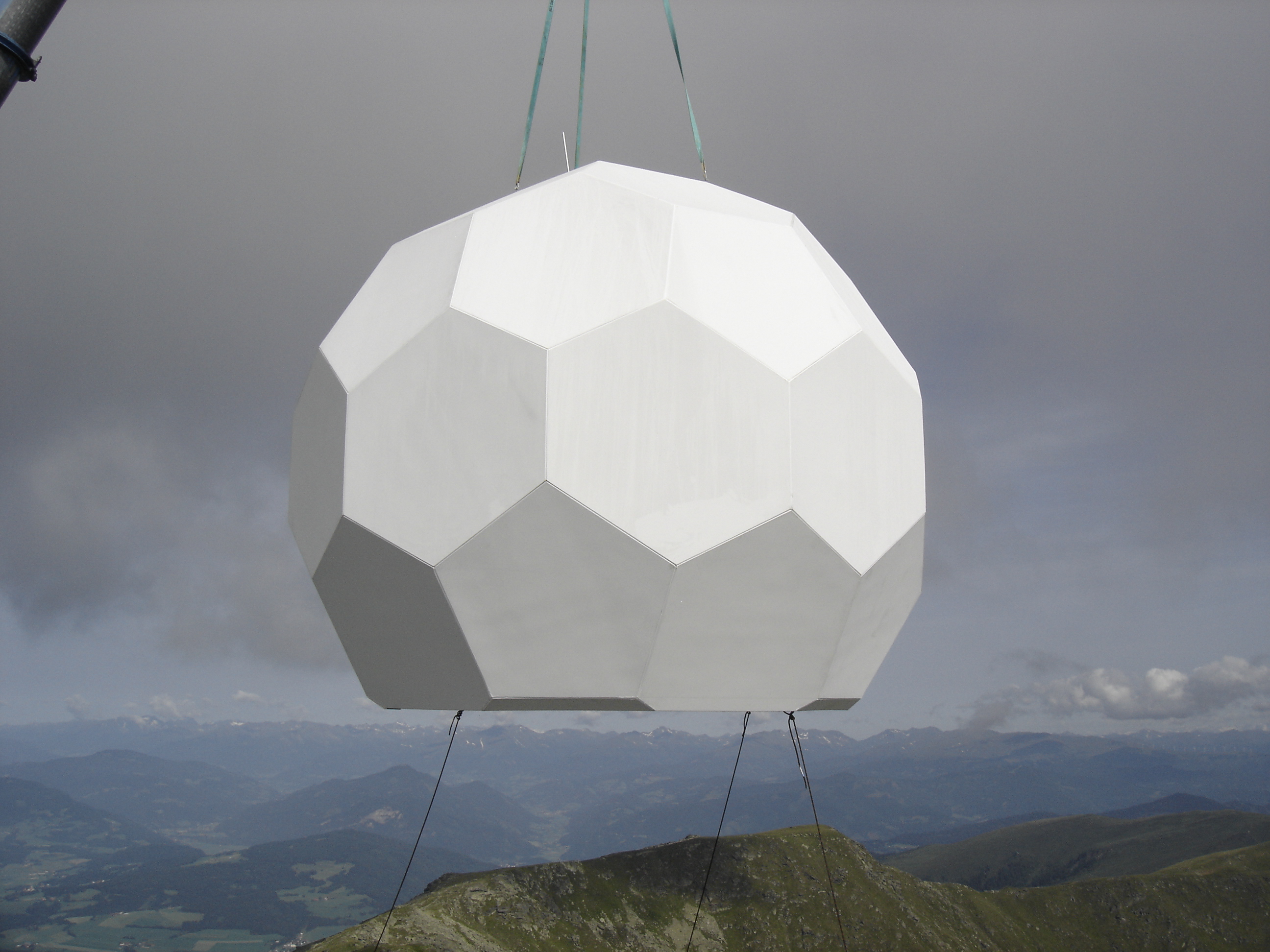
 Stealth Radome Technology for Dual Pol Polarimetric Radar
 |
|
Figure 13. Stealth Radome for dual polarized polarimetric weather radar. |
Appealing to the scattered field equation for the difference between vertical and horizontal electric field components, what is required for Stealth polarimetric radar is Esvp - Eshp @ 0, where the scattered fields are complex numbers with both amplitude and phase. From the scattered field equation, the mathematical solution is a complicated problem dependent on radome geometry, panel shape and curvature and impedance matching electronic signature as well as pointing direction of the radar antenna. As shown in Figure 13, the result is the innovative esthetic style of the next generation Stealth radome for dual polarized polarimetric radar. The Stealth radome artistic features and technology are similar to the sharp lines and surface angles recognized in the Stealth F117 Nighthawk fighter jet, which is designed to avoid detection using a variety of stealth technologies that reduce radar reflections and emissions.
Stringent sidelobe level (SLL) envelope requirements apply generally in Satcom applications that employ satellites in geosynchronous orbital slots. The paramount operational requirement is that the earth station antenna (ESA) neither illuminates via sidelobes other satellites in the geosynchronous plane nor receives signals, via sidelobes, from such satellites. Compliance with the SLL envelope requirements assures that such crosstalk is at an acceptable level. For satellite earth station transmit antenna patterns, the key issue is SLL compliance with FCC Part 25.209 regulations (as well as similar requirements for Intelsat IESS-207 and IESS-601, Eutelsat EESS 500 and Asiasat) known as:
![]() Compliance of Satellite Earth Station Antenna Patterns
Compliance of Satellite Earth Station Antenna Patterns
29-25*log(Q )
We wish to point out that the enclosure of the antenna in a fixed panelized radome introduces a critical and novel distinction between operational system performance and performance validation by certification tests. The reason is that when the antenna is operational, both the antenna and radome are stationary with the antenna pointed at the satellite. In contrast, when the antenna is undergoing certification tests, the radome and satellite are at rest with the antenna moving to construct the sidelobe pattern. Under such circumstance, the antenna aperture blockage afforded by the radome framework continuously changes as the antenna sweeps over the sky. One therefore must make sure that both the operational antenna/radome sidelobe pattern and the antenna/radome under test both meet the intended specifications.We also note that in general there is a reduced FCC operational requirement to limit SLL outside the geosynchronous plane 32-25*log(Q ). Such a reduced requirement is measured by an elevation antenna pattern cut. This comment is of practical significance for center fed antennas. In FCC/INTELSAT applications, 4 struts that run diagonally to the outer portion of the dish typically support the feed/subreflector. The scattering by these struts, or by any long scatterer illuminated by the antenna, is in the plane transverse to the axis of the strut. The strut scattering degrades the pattern in diagonal planes. In consequence, such FCC/INTELSAT qualified antennas often do not generally comply with the SLL envelope in diagonal planes. It is of tremendous practical import that the strut scattering does not degrade the pattern in either principal plane. Such antennas comply with SLL requirements in both azimuth and elevation cuts. This allows elevation cuts to be used as validation pattern measurements in transmission using a cooperating satellite. With some limitations, the like measurement cannot completely be performed on azimuth cuts as it involves sweeping the antenna main beam along the geosynchronous arc with unacceptable illumination of nearby geosynchronous satellites. Under such circumstances, antenna symmetry may be assumed for the equivalence of both elevation and azimuth pattern cuts.
Here is where the complication begins. Introducing the radome into the antenna pattern reduces the antenna symmetry to that of the radome framework symmetry. Elevation and azimuth pattern cuts for the antenna/radome combination are now independent. Indeed, it is often the objective of the radome designer to put the scattered energy into the elevation cuts so as to minimize sidelobe error for the azimuth pattern. Even though scattered energy is very small, it has to go somewhere. The problem for the radome designer is that the antenna sidelobe energy is very small as well. Fortunately, the radome designer has two tools at his disposal. The first tool is impedance matching to reduce the framework scattering loss. The second tool is radome geometry to orient the framework members to scatter energy in appropriate directions.
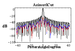
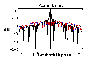
Figures 14 through 17 illustrate the distinction between the measured pattern of the radome-enclosed antenna under test and the actual pattern of the radome/antenna system (the pattern on the sky). The figures are for AFC's 10.4m (31ft) diameter radome protecting a Viasat 4.5m earth station antenna. Operation is at C-band for linear polarized transponders. Figure 15 is the actual azimuth cut pattern, the illumination along the geosynchronous arc when the ESA is boresighted on the primary satellite. Figure 16 is the actual elevation cut pattern. In contradistinction, the measurement of the radome/antenna is made by rotating the antenna inside the radome and observing the pattern at a fixed far field point. Each incremental rotation of the antenna with respect to the radome modifies the set of illuminated framework joints (framework shadow). The cumulative effect is significant. Figures 14 and 16 show the measured sky pattern. For this particular antenna, both measured and sky patterns sets clearly comply with the SLL envelope. Compared to the sky SLL patterns, the measured azimuth pattern has somewhat higher and less distinct sidelobes beyond -9o. From the above discussion, modern measured pattern with computational integration methods fail to predict antenna performance degradations for radome enclosed antennas.
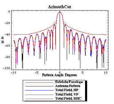 |
| Figure 14. The azimuth cut pattern on the sky as radiated by the radome/antenna configuration. The pattern is fully compliant with the SLL envelope. |
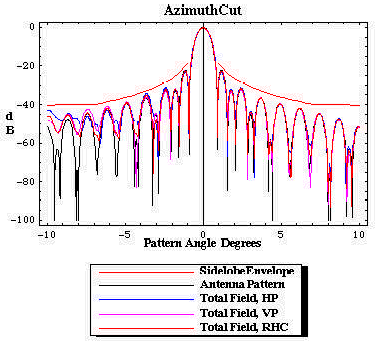 |
| Figure 15. The apparent azimuth cut pattern measured by rotating the antenna in the radome. The measured pattern is compliant with the SLL envelope. |
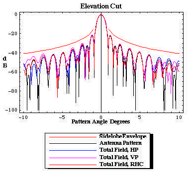 |
| Figure 16. The elevation cut pattern on the sky as radiated by the radome/antenna configuration. The pattern is compliant with the SLL envelope. |
 |
| Figure 17. The apparent elevation cut pattern measured by rotating the antenna in the radome. The measured pattern is compliant with the SLL envelope. |
Radome Design Considerations for Satellite Earth Stations
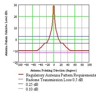 |
| Figure 18. Regulatory antenna pattern requirements along with radome scatter pattern level as a function of radome transmission loss. |
The FCC, Intelsat and other regulatory agencies have yet to come to grips with a set of standards suitable for a radome-enclosed ESA. While radome design criteria directs scattered energy into the elevation plane where SLL interference is a non-issue, compliance regulations preclude such an obvious solution. Another issue relates to ESA site compliance measurements as performed for a regulatory agency and radome scattering into the far out sidelobes. For example with respect to AFC�s 10.4m (31ft) diameter radome protecting Viasat�s 4.5m ESA described in Figures 14 through 17 above, Figure 18 constructs the regulatory 29-25*log(Q ) antenna pattern envelope superimposed over the scatter pattern level. The scatter pattern levels (dBi units) are shown as a function of radome transmission loss. While ESA site compliance measurements are typically limited to scan angles +/- 10-degrees or less, Figure 18 demonstrates that the radome far out scattering pattern level actually causes non-compliance issues at pointing directions not measured during certification tests; namely 12-degrees for 0.5 dB transmission loss and 18-degrees for 0.25 dB transmission loss. On the other hand, due to the limited scan range with cooperating satellite measurements, certification tests would be found compliant. It is only when the radome transmission loss is less than 0.1 dB that strict compliance is recorded for elevation and azimuth pattern measurements.
Over standard communications bandwidth, the dilemma for radome electromagnetic design is that radome technology, through impedance matching and radome panel geometry, yielding near zero (< 0.1 dB) transmission loss is beyond the present state-of-the-art. As pointed out earlier, antenna engineers have the luxury of only 4 feed support struts oriented at 45-degrees angles. Their antenna pattern non-compliance is masked by the specific elevation and azimuth antenna pattern cut directions. In contrast, radome engineers have no such comfort. Numerous radome shadow members, oriented at various angles, preclude such an obvious deception.
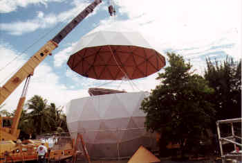 |
| Figure 19. Construction of AFC's 41-ft diameter radome shielding a Vertex 8.1m satellite earth station. |
The following four Adobe Acrobat PDF files illustrate radome-enclosed earth station SLL performance. The azimuth and elevation pattern measurements are for a GD Satcom Vertex 8.1m legacy antenna protected by AFC's 12.6m (41ft) diameter radome as shown in Figure 19. These measurements were conducted to verify Intelsat certification for C-band satellites on circular polarized transponders.
The four pattern measurements are:
- Azimuth pattern cut for copol and xpol polarization.
Transmit RHCP at 6.339 GHz.- Azimuth pattern cut +/- 1-degree for copol and xpol polarizations.
Transmit RHCP at 6.339 GHz.- Elevation pattern cut for copol and xpol polarizations.
Transmit RHCP at 6.339 GHz.- Elevation pattern cut +/- 1-degree for copol and xpol polarizations.
Transmit RHCP at 6.339 GHz.
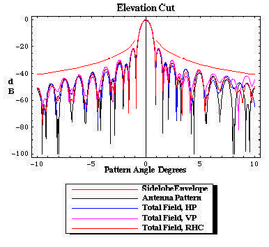
The above cooperating Intelsat regulatory pattern measurements show "compliance" for azimuth patterns and "non-compliant" for elevation patterns. For the elevation pattern cut, SLL compliance issues begin at the measured 8-degree scan angle where the SLL pattern is approximately �46 dB down.
AFC manufactures, markets and sells worldwide satellite dish antennas, radomes, antenna feeds and ultra low loss waveguide transmission line Tallguide �. Our customers serve the broadcast, communications, radar, weather and cable industry, defense, government, and government agencies worldwide. AFC's quality control manufacturing standards are certified under ISO 9001 : 2015.
Top of Page Return to AFC ProfileReturn to Radome Network Home Page.
Telephone (352) 687-4121 Fax(352) 687-1203 E-mail sales@afcsat.com
Tallguide is a Registered Trademark of Antennas for Communications Stealth is a Registered Trademark of Enterprise Electronics Corporation Copyright � 2002 - 2020 Antennas for Communications