Antennas for Communications (AFC) Logo

Dielectric Radome Advantages


Return to AFC Profile   Return to Radome Network Home Page Return to Radome Network Home Page.

red_ball.gifAFC's dielectric radomes have many advantages over other radomes. For any radome type, panel edges are reinforced into flanges for adjacent panel assembly. When the radome panel flange framework is a dielectric material, the radome is called a Dielectric Space Frame (DSF). In contrast, when the panel framework is metal, the radome is called a Metal Space Frame (MSF) radome. DSF radomes may be constructed as a TM thin membrane, SL solid laminate, 2L or SFC sandwich, CLS or THS. Recent technology innovations, CLS and THS, provide broadband, Ka-band and extremely high wind structural performance. Often a sandwich or THS wall is used where thermal insulation or where high frequency and low transmission loss requirements prevail. When the panels are assembled, the panel array forms a truncated spherical surface with a spherical, geodesic or Stealth geometry, where Stealth is a unique technology for which the radome exhibits identical performance independent of radar polarization or pointing direction.

red_ball.gifAntennas for Communications (AFC) has been deploying radomes worldwide since 1987 and composite material antennas since 1972. Our radomes have been subjected to every environmental condition. Over the years, many of these radomes have also been subjected to hurricane, typhoon and cyclone winds, Antarctic cold and desert heat. Each of these radomes experience constant environmental exposure to sunlight, UV and corrosive atmosphere as well as the inconsistencies of manufacturing tolerances, installation errors and infrequent maintenance. End-of-life issues generally characterize this slow degradation process. Using natures environmental test laboratory as a guide, we have analyzed these successful radomes using the time dependent nonlinear Finite Element Analysis (FEA) tools at our disposal. Our concern is how much safety factor margin do we need to guarantee a life-time of structural performance. It is for this reason that AFC has defined lifetime radome structural safety factors by a criterion based on the geometric deformation of the radome shell leading to catastrophic failure and a critical target wind speed. Such geometric instability is called General Buckling. Based on those FEA analyses for a minimum 20-year lifespan, we have achieved a criterion on General Bucking safety factors:

General Buckling Safety Factors > 1.9

What this means is that for a minimum 20-year lifespan and since wind pressure forces on a radome increase as the square of the wind speed, the General Buckling criterion means that radomes have to be designed with a critical wind speed 40% larger than the maximum wind speed specification requirements.

Imedance Matching to Reduce Framework Scattering Loss. grn_ball.gifRadome transmission loss is composed of two major loss contributions. The first contribution and typically the smallest is the ordinary insertion loss of a signal passing through the radome wall. The second loss contribution comes from signals scattering off the radome panel flange framework. For most frequency bands, framework scattering loss is several times larger than the radome wall insertion loss. When demanding RF transmission loss specifications and structural environmental (wind) loads compete with requirements, dielectric radome RF performance may be optimized by a process called impedance matching. Adjacent dielectric panel flanges form a framework blocking (shadowing) the antenna aperture, which behave as reactive RF loads. Just as the microwave engineer adds circuit elements to impedance match the reactance of a load over a required bandwidth, so does the radome engineer. By embedding circuit elements into the dielectric flange framework, scattering loss is "tuned out" significantly improving transmission loss. In contrast, the metal space radome framework blocks all the RF energy. You must take what you get with a MSF radome without any method or means of improvement. For dielectric radomes, on the other hand, it is the wealth of impedance matching compensation alternatives for any frequency band that the DSF radome outshines any substitute. With impedance matching, a dielectric radome is tuned to customer requirements without compromise. AFC has performed considerable broadband impedance matching work over the 0.1 to 44 GHz frequency range.

Top of Page.

red_ball.gifAFC's dielectric panels are a molded one piece process forming a rigid panel structure. The regid panels eliminate wavy, flapping panel membranes and eliminates the need for pressurization to reduce oil-canning, sound/vibration noise, microphonics and fatigue failure characteristic of metal space frame (MSF) radomes. In contrast, without pressurization, metal space frame radomes fail to meet wind load speed requirements. With a need for pressurization, a metal space frame radome relies on prime power to energize the blower equipment to survive maximum wind loads.

Dielectric Space Frame (DSF) Radome with Metal Space Frame (MSF) Radome is Background. Metal Space Frame (MSF) Radome with Weinkled, Wavey, Flappy Panels.
Dielectric Space Frame (DSF) Radome with Metal Space Frame (MSF) Radome is Background. Metal Space Frame (MSF) Radome with Wrinkled, Wavy, Flappy Panels.

For unattended radome sites, pressurization blowers add another failure mechanism---thereby reducing up-time operational performance and making the radome survival dependent on prime power outages.

Metal Space Frame Corrosion grn_ball.gif Dielectric radome panels have no metal beams in their framework, which corrode in harsh or salt environments. Minimal maintenance is required for dielectric radome panels. In contrast, the metal space frame (MSF) structural framework members experience corrosion, which washes onto the radome surface, adjacent panels members and adjoining framework beam structure. Not only is corrosion a maintenance problem, but from an RF point of view, corrosion creates a continuous surface of numerous semiconductor diode mixers. These mixers generate intermod interfering signal products in the presence of high power, multi-frequency/carriers, characteristic of modern satellite, radar and communications systems. In contrast, AFC's dielectric radomes are intermod free.

Top of Page.

red_ball.gifDielectric radomes have no dissimilar metal corrosion problem. Dissimilar metals (for example, Aluminum and Steel) create corrosion in the presence of water moisture. In contrast to dielectric radomes, metal space frame radomes use dissimilar metals at every bolt that joins the metal framework. In addition, since metal space frame radomes require a metal base ring for structural support, a dissimilar metal problem exists between the base framework panels and the base ring. Dissimilar metal corrosion is another source of diode mixers. These mixers further generate intermod interfering signal products in the presence of high power, multi-frequency/carriers. In contrast, AFC's dielectric radomes are intermod free.

grn_ball.gifAFC introduced the use of corner nodal bolt technology to transfer corner loads to the rest of the radome panels. This creative solution eliminates the need for corner hub load distribution caps common to metal space frame radomes. Nodal bolt technology significantly reduces blockage transmission loss. In contrast, corner hub caps increase antenna blockage and increase radome transmission loss and noise temperature.

red_ball.gifWhen service or antenna update schedules demand radome access for large antenna part removal or entry, dielectric panel members are easily removed, reinserted and resealed. For tactical systems, panel section removal is an alternative to fixed large entry/exit doors. Panel section removal hides the nature of mobile vehicle tactical systems and removes door blockage from degrading system performance.

2-Layer Sandwich panel Removal View 1. 2-Layer Sandwich Panel Removal View 2.

grn_ball.gifWith the DSF panel flanges internal to the radome, dielectric space frame hardware are not exposed to the environment.

red_ball.gif AFC has an optional super-hydrophobic coating, Hydrolam 2000, which meets the demands of real systems. This coating forms a bond to the radome surface, is abrasion resistant and may be reapplied in the field, should the radome surface be damaged. AFC's hydrophobic coating retains its vitality and remains bonded to the surface years longer than any commercial surface preparation.

Top of Page.
Tedlar Pealing Problem.
Metal Space Frame (MSF) Radome
with Tedlar Pealing

grn_ball.gif AFC's unique proprietary process solves the Tedlar pealing problem, characteristic of metal space frame bonded composites with dissimilar thermal expansion coefficients.

red_ball.gifIn order to simplify field installation, DSF radome panel sides are letter coded at the factory, "A" through "Z". Since the radome has several different panel types, the letter coding enables installation personnel to assemble like panel code letter edges without relying on misplaced assembly instructions.

grn_ball.gif
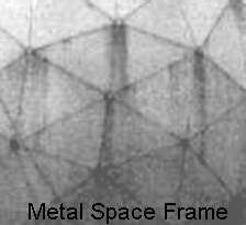
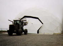
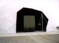
For most normal site installations, little to no coordination is required between the radome/installation team and the foundation site preparation group. The reason is that DSF radomes do not require a metal base ring (compression ring) or precast foundation anchor bolts. (In contrast to metal space frame procurements, no base ring disagreements need take place over whether the base ring is part of the radome or site civil works price estimates.) Now common practice, AFC has pioneered and field tested for the U.S Army and USAF, a radome base panel assembly technique with the radome foundation which eliminates the need for precision foundation bolt placement. Using the radome base panels as a guide template, wedge anchor bolts are bored into the foundation at installation by the installation field crew. In contrast to a metal space frame radome, no foundation survey, template preparation and accurate anchor bolt insertion into the wet foundation or compression base ring interface need be scheduled or timing anticipated. Thus foundation construction and radome installation become independent activities----removing the usual need for precise coordination. For example, the DSF radome wedge anchor bolt technique has been used with 80ft (24.4m) diameter radome 200 mph wind speed location sites. Indeed, removing the need for accurate and meticulous foundation and site coordination assures a timely and successful installation, even under the most trying of circumstances.

Top of Page.

AFC manufactures, markets and sells worldwide satellite dish antennas, radomes, antenna feeds, microwave and waveguide components and ultra low loss waveguide transmission line Tallguide ®. Our customers serve the broadcast, communications, radar, weather and cable industry, defense, government, and government agencies worldwide. AFC's quality control manufacturing standards are certified under ISO 9001 : 2015.

Return to AFC Profile   Return to Radome Betwork Home Page Return to Radome Network Home Page.

Antennas for Communications
2499 SW 60th Ave, Ocala, FL 34474
Telephone (352) 687-4121 Fax(352) 687-1203 E-mail sales@afcsat.com


Tallguide is a Registered Trademark of Antennas for Communications
Copyright © 1996 - 2020 Antennas for Communications