 Radome Capabilities
- Advantages of Radome Protection
- Basic Construction Techniques
- Radome Lifetime, Mechanical and Structural Considerations
- Design Enhancements to Maximize Performance
- Random Panel Geometry Eliminates Coherent Reflections
- Impedance Match Tuning a Dielectric Radome
- Filter Design for Radomes
- Eliminating Water Accumulation
- Selecting a Radome to Match Your Requirements
- Operating Frequency Considerations
- Initial Cost Approximation
- Complete Radome System Capability
- Installation Services Throughout the World
- Support Equipment for Full Operational Status
- Advantages of Selecting AFC as Your Radome Source
- Experience of Over 30 Years
- Capabilities to Match Your Fast Response Requirements
- Quality to Last
- Related Standard and Specialized Products
- Standard and Customized Antennas
- Tallguide Ultra Low Loss Waveguide
 Advantages of Radome Protection
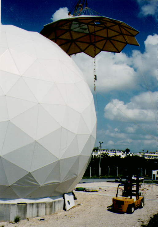
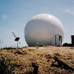
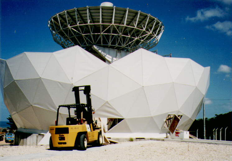
Radar domes, or Radomes, are RF window prefabricated geodesic structures used to shelter antennas. Typical applications include antennas for radar, telemetry, tracking, communications, surveillance, and radio astronomy. The first radome was constructed 60 years ago; they are currently in use throughout the world, from the tropics to the arctic.
The principal purpose of a radome is to shield the antenna from the environment. This improves system availability since the antenna is not affected by winds, rain, or ice. It can also improve antenna performance since high winds or temperature variations can distort the shape and pointing direction of the reflector or phased array.
Radomes also provide a benign environment for any electronics, and personnel, that must be located near the antenna. This is especially significant in harsh weather, such as temperature extremes, blowing sand or dirt, salt spray, and freezing rain.
Radomes have proven to be very effective when considering life cycle costs. Since the antenna is in a protected environment, maintenance costs are held to a minimum. The structural requirements of the antenna and pedestal are less stringent, resulting in reduced fabrication and installation costs plus the use of smaller positioning motors.
Further, a unique advantage of radomes are that dome structures are aesthetically pleasing. Radomes are also very effective in concealing the type of equipment inside the dome.
 Basic Construction Techniques
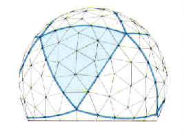
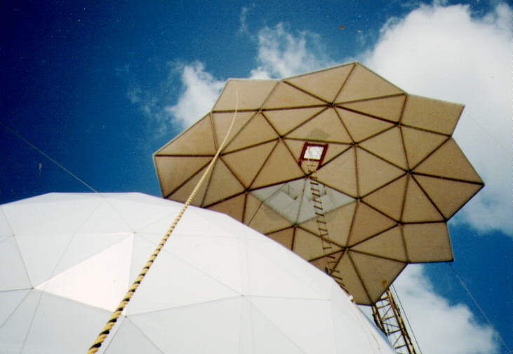
Rigid radomes are designed using the principles of a geodesic dome. This technique uses straight or circular arc structural elements in tension, arranged in a framework of geometric patterns such as triangles and hexagons. This design results in a structure that provides maximum volume with minimum material, reduces stress and weight, and may be tailored to meet exacting electromagnetic scattering requirements.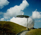 |
 |
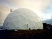 |
AFC currently offers six different types of rigid radomes: the TM thin membrane wall dielectric space frame (DSF), the SL solid laminate, 2L or SFC two and three layer sandwich DSF radome, CLS and THS. The term Dielectric Space Frame with acronym DSF refers to the dielectric panel flanges surrounding the panel wall, which forms a framework characteristic of the panel shapes. Recent technology innovations CLS and THS furnish broadband, Ka-band and extremely high wind structural operation. Each radome type provides unique operating characteristics and benefits. Although all types may be used in a variety of different applications, the thermally insulated radome accommodates a temperature compensated environment for electronics or personnel. Radome size varies from several inches to 150 ft. in diameter. For more details, see advantages of dielectric radome technology.
Radome Lifetime, Mechanical and Structural Considerations
In a typical radome design, maximum panel dimensions are chosen for worldwide shipment. This permits use of a standard ISO ocean shipping container and trucks and simplifies panel handling during installation.
Most radomes are designed to operate with wind speeds of up to 67 m/s (150 mph) or more, and snow or ice loading of up to 235-kg/m2 (50-lb/ft2). To minimize electromagnetic, RF imperfections, radome structural strength must be measured against the demands for better RF performance. What this means is that the radome structure supporting the wind, snow and ice loads must be designed strong enough to meet environmental requirements for the radome lifetime. Beefing up the radome panel framework or making the wall sturdier just degrades RF performance. To enhance RF performance, this balancing act between a stronger structure with heavy-duty sized members and RF performance determines that radomes are designed with structural safety factors determined by radome lifetime requirements. It is for this reason that AFC has defined radome structural safety factors by a criterion based on the geometric deformation of the radome shell leading to catastrophic failure and a critical target wind speed. General Bucking is the term used to describe such deformation processes. Based on a minimum radome 20-year lifespan, a General Buckling Safety factor greater than >1.9 criterion is chosen .
The structural load bearing capabilities of a radome are a function of radome diameter and geometry, frequency, panel shape, number of panels and both the flange and wall design in conformance to the radome RF performance. While each radome size uses a common mold and tooling set, as a result of unique specifications, each radome is customized to match particular system environmental requirements over the lifetime of the radome.
Design Enhancements to Maximize Performance
Antenna design engineers believe their antennas are perfect creations. Therefore, the ideal radome would appear totally transparent to any electromagnetic signal. Since this is not possible, radomes must be designed to minimize the impact of the radome on the enclosed antenna. Application requirements determine the importance of signal distortions such as insertion loss, boresight error, and scattering into the antenna sidelobes. AFC employs several different techniques to improve performance goals.Random Panel Geometry Eliminates Coherent Reflections
 Radome geometry framework panel members cause scattering transmission loss errors whenever the framework blocks (shadows) the antenna aperture. If the radome were constructed of identical panels, the total scattering loss would be summed by the repeated error. To eliminate this problem, many AFC radomes utilize a quasi-random or pseudo-random panel design.
Random panel design is achieved by starting with one of the Platonic Forms; which is a method of dividing a sphere into 4, 6, 8, 12, or 20 identical subdivisions. One of the subdivisions is then further divided into panels of different shapes. By repeating this pattern, a complete sphere can be constructed that will provide the quasi-random panel distribution without extensive fabrication costs.
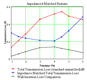
Impedance Match Tuning a Dielectric Radome
|
Dielectric DSF radomes are assembled from multiple panels. At the panel edges, the dielectric material is reinforced into flanges to support structural loads and mechanical fasteners. Assembled, the panel flange framework blocking (shadowing) the antenna aperture, act as obstacles scattering RF signals according to radome geometry, flange electronic signature, frequency and the enclosed antenna pattern and polarization. Scattering loss is often 4 to 100 times larger than the ordinary wall insertion loss. To compensate for the scattering loss, AFC impedance matches, "tunes", the radome framework by embedding circuits into the flange framework. The circuits cancel the reactance of the dielectric framework. To even further help reduce the influence of framework scatterers, panel geometry is chosen to minimize boresight shift and sidelobe perturbations. |
Filter Design for Radomes
A radome is an electrical filter constrained to support environmental wind, snow and seismic loads. This filter, made real by one of the six dielectric radome technology types, determines that our radomes have appropriate structural safety factors for the lifetime of the radome. To comply with the structural constraints, the radome is made stronger by adding more filter tuning elements to the filter design process. The combined structure - filter implementation achieves optimal RF performance for the particular frequency band or multiple bands of interest. Several of the filter types provide excellent thermal insulation combined with minimal transmission loss over the selected frequency bands.Eliminating Water Accumulation
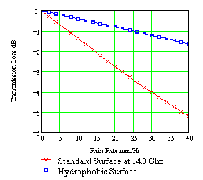
| Additive Rain Transmission Loss | Additive Rain Noise Temperature |
 |
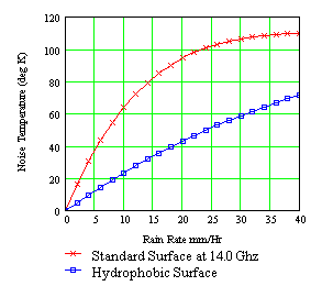 |
With any radome, water tends to collect on the exterior surface and run off in sheets; significantly affecting performance. AFC utilizes a proprietary technique to provide a long lasting super-hydrophobic surface, called Hydrolam 2000. This causes the radome to remain dryer, water to bead and run off in rivulets instead of sheeting. A hydrophobic surface helps to inhibit ice adhesion.
Selecting a Radome to Match Your Requirements
In most applications the two primary factors in selecting the type of radome are performance and cost. Additional considerations over the radome lifetime may include environmental requirements, such as thermal insulation, ease of transportation, installation, snow loading and wind/gust rating. All applicable factors must be considered in order to insure an optimum match.Operating Frequency Considerations
In general, dielectric radomes are broad band structures suitable for operation over a relatively wide range of frequencies. SFC Sandwich radomes are more frequency specific since the thickness of the core is varied to achieve the desired insertion loss for a particular frequency band. In general, the SFC radome frequency response forms a low pass filter with the cut-off frequency corresponding to the upper frequency limit. The filter design process for CLS and THS technology radomes allow for simultaneous RF frequency band superior performance and structural strength.Initial Cost Approximation
The initial cost of a radome is primarily dependent on the size of the structure and increases as the radome surface area (radome diameter D2). Note that the material and labor costs in a radome will increase geometrically with the diameter. This is due to the fact that doubling the diameter of a sphere will increase the surface area by a factor of four.
Complete Radome System Capability
In addition to radome design and fabrication, AFC also offers a complete turn-key system capability. This includes complete installation, performance verification, support equipment, and extended term maintenance. The only aspects not covered by AFC are the antenna and the site selection. While these two items are normally dictated by the mission to be performed, AFC can support the program with a site survey.Installation Services Throughout the World
 |
 |
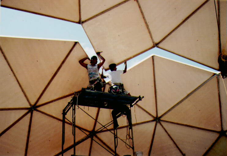 |
AFC maintains an installation team with the experience and capability of installing a radome at any site in the world. Typical services include foundation interface and design load requirements, radome assembly, and performance verification. Where a customer wishes to participate in the installation, AFC is able to provide a technical site supervisor. An installation and maintenance manual is a standard part of the radome delivery so that a customer supplied installation team or maintenance personnel may complete the project. Extended term maintenance contracts are available for our radomes. These contracts cover both preventive maintenance and repair. The repair aspect frequently includes fabricating replacement panels or accessories.
Accessory Equipment for Full Operational Status
Accessory equipment to customize a radome for a particular application may include AC power distribution, interior lighting, ventilation, heating/air conditioning, aircraft warning lights, lightning protection, doors and hatches. AFC will provide and/or install required accessory equipment to insure that the system achieves full operational status within a minimum time frame. AFC also maintains an inventory of standard accessory equipment to insure a fast response to any failure.Advantages of Selecting AFC as Your Radome Source
Most radome solutions are adapted from standard off-the-shelf COTS units. In some cases, radomes must be individually designed and fabricated to satisfy a unique set of requirements. Accomplishing design requirements in a timely manner requires practical experience, engineering talent, facilities, effective administration, and a willingness to commit these resources to the task.Experience of Over 30 Years
In 1979 Microdyne acquired Antennas For Communications (AFC), an antenna manufacturing company started in 1972. This acquisition enabled Microdyne to offer complete systems for both uplink and downlink satellite communications. In June 1991, AFC was purchased by an employee group. With expansion into the radome product line, more than 900 radomes have been manufactured and installed worldwide from the dessert heat and tropics of the Amazon to the cold of the Antarctica.Capabilities to Match Your Fast Response Requirements
AFC has the engineering, manufacturing, and administrative capabilities to respond to your requirements. For example, AFC signed a "quick reaction" contract to design and fabricate two, 41 foot (12.6m) dielectric radomes for the US Army. The radomes were completed and ready for shipment 60 days after receipt of the order. An additional three weeks was required for installation and full performance verification. This example is typical of AFC willingness to commit their resources to meeting your requirements.Quality to Last
AFC's quality control manufacturing standards are certified under ISO 9001 : 2015 and supports FAA-STD-016A and MIL-I-45208A Quality Program Requirements. Tailored to insure compliance ....fabrication process controls and program tests, record and data audits ....at each and every step in radome implementation. This assures top quality, in all aspects, of the final product.Related Standard and Specialized Products
Antennas for Communications offers specialized products to provide superior performance in a variety of applications. These products include antennas and waveguide components.Standard and Customized Antennas
AFC's standard antenna line includes dish antennas from one to five meters in diameter. These antennas are currently in use throughout the world for a wide variety of commercial and government customers. The primary applications include microwave links, Television Receive Only (TVRO) downlinks, and satellite uplinks.
AFC also maintains a complete design and fabrication capability to provide custom antennas for specialized applications. Since this capability is an integral part of the company, AFC is able to provide a fast response for customized antennas at a competitive price.
Tallguide Ultra Low Loss Waveguide
The Tallguide� product line consists of a series of ultra low transmission loss rigid waveguides, mode suppressors and transitions which provide exceptionally low transmission losses in comparison to standard waveguide. The attenuation per 100 feet is typically one-tenth that of conventional waveguides. Allowing the Tallguide inter-facility run to be designed for convenience, from the control room to the antenna, this increased efficiency can result in a significant reduction in system costs. Like waveguide, without the need for specialized installation tools, the product line includes all necessary hardware for operation in the 5 to 100 GHz frequency range.
AFC manufactures, markets and sells worldwide satellite dish antennas, radomes, antenna feeds, microwave and waveguide components and ultra low loss waveguide transmission line Tallguide �. Our customers serve the broadcast, communications, radar, weather and cable industry, defense, government, and government agencies worldwide. AFC's quality control manufacturing standards are certified under ISO 9001 : 2015.
Telephone (352) 687-4121 Fax (352) 687-1203 E-mail sales@afcsat.com
Tallguide is a Registered Trademark of Antennas for Communications
Copyright � 1996 - 2020 Antennas for Communications