 Radome Installation and Assembly
|
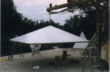
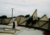
There are two general radome assembly methods. AFC's installation crews classify the two techniques as the crane procedure and the scaffolding procedure. Depending on site conditions and radome diameter, often both assembly routines are combined in an economical fashion. In the crane assembly method, Figure 1, the entire radome is assembled on the ground. Using a crane for support, radome assembly starts with the top zenith panels. As the crane lifts these panels, new rows are added until the radome is completely assembled. Crane lift sling attachment radome points are usually changed to accommodate the partially completed structure.
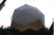
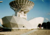
In contrast, the scaffolding procedure, Figure 2, starts with the radome base. Assembly starts at the base layer, progressing toward the radome top. All bolts are torqued to proper settings. Typically, scaffolding or man-lifts are used as work platforms. When a crane is available, the bottom layers are assembled until the diameter of the antenna is circumscribed. At the end of each day, the radome is secured by nylon ropes. Equipment exposed to the weather is covered until radome water leak testing is completed.
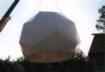
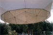
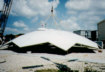
Adjacent to the radome or tower assembly, the radome crown section is assembled on the ground using the crane procedure. Starting with the zenith hub panel attached to the crane, the radome panels are bolted together. By raising the crane slightly, more panels are added to the crown. When the ground level crown area assembly is finished, the crane raises the crown and positions it over the topless radome. Providing stability, guidance and safety, safety lines held by ground men make fine corrections to the top cap location. The radome top cap is then bolted in opposite locations until fully secured. At sites where a crane cannot be used, a manual process is started. After erection of a working scaffolding platform, panels are hoisted from the radome base to the platform by way of hooks and ropes. As an alternative to scaffolding, a man-lift may be used. Continuing this process, each panel is attached to the radome until the top zenith panel and hub assembly is bolted in place. Outside procedures, such as caulking the seams and detaching the crane (when used) proceed next by escaping from the top hatch and repelling downward. The attachment of lightning rod assemblies, vents, emergency lights, blowers, electrical panels and interior lights are installed according to configuration site instructions. Water testing of the dome, when water is available, is used to identify any leaks. Such leaks are corrected. Lastly the site is to be cleaned.
AFC manufactures, markets and sells worldwide satellite dish antennas, radomes, antenna feeds and ultra low loss waveguide transmission line Tallguide �. Our customers serve the broadcast, communications, radar, weather and cable industry, defense, government, and government agencies worldwide. AFC's quality control manufacturing standards are certified under ISO 9001 : 2015.
Dielectric Space Frame Radomes Return to AFC Profile Telephone (352) 687-4121 Fax (352) 687-1203 E-mail sales@afcsat.com Tallguide is a Registered Trademark of Antennas for Communications Copyright � 1998 - 2020 Antennas for Communications |