


Antennas for Communications
Radome Network
High Performance Dielectric Radomes
 |
 |
 |
 |
 |
 |
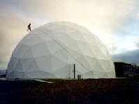
| NOAA NWS Radome Doppler Weather Radar |
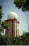
GBS Ground Terminal Radome |
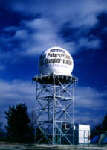
Arctic Ka-band TT&C Radome |
Sandwich Radome |
Welcome to AFC's Radome Network
A radome is a weatherproof geodesic prefabricated building structure that protects radar and antenna systems from extreme weather: wind, blowing sand, snow, ice, rain, ultra violet sunlight, temperature, fungus and corrosion.AFC's high technology all dielectric radome capability combines the expertise of materials science, geodesic domes, prefabricated building structures and electromagnetics. AFC manufactures six types of dielectric radomes: TM; SL; 2L; SFC; CLS; and THS. Each radome technology type behaves as an electrical filter constrained to support environmental and wind load requirements. Recent technology innovations CLS and THS provide simultaneously high frequency, Ka-band, broadband and very high wind structural performance. The six technology types identify themselves primarily by the radome wall construction, which are incorporated into Spherical, Geodesic, Silo or Stealth radome geometries. For dual-pol polarimetric weather radar, Stealth introduces a unique technology where the radome exhibits identical performance independent of radar polarization and pointing direction.
As part of the radome panel molding fabrication process, the dielectric panel edges are reinforced into flanges for adjacent panel assembly. When assembled to the other panels, the panel array forms a truncated spherical radome surface. After assembly, the radome dielectric panel flanges form a framework establishing the general terminology Dielectric Space Frame (DSF) for AFC's radome products. Depending on radome wall parameters, adjacent panel flanges may also serve as environmental load bearing beams or struts. Each panel is a molded one piece unit without bond or seam lines. Individual panels may be doubly curved or flat yielding a faceted or spherically smooth appearance. Radome applications include radar and weather radar systems, air traffic control, telemetry, satellite communications, DSCS, MILSTAR, MET, SBIRS, NOAA, NASA and receive-only listening systems.
Not commonly known to most engineers, radome transmission loss is composed of the insertion loss from the RF signal passing through the radome wall and from the scattering loss off the panel flange framework. In most cases, the scattering loss from the framework is several times greater than the wall insertion loss.To reduce scattering loss, AFC engineers pioneered a technique known as impedance matching to "tune out" framework scattering loss. RF circuit elements are laminated into the dielectric flanges to impedance match scattering loss. Any of the six radome technology types may be impedance matched.
Transmission Loss Improvements by
Adding Impedance Matching Circuits
to Reduce Framework Scattering at C-band.To enhance radome RF performance, a filter design process implements a stronger structure at maximum rated wind speed with improved RF operation. This filter, made real by one of the six dielectric radome technology types, determines that our radomes have appropriate structural safety factors for the lifetime of the radome. It is for this reason that AFC defines radome structural safety by a General Buckling criterion based on the geometric deformation of the radome shell, which defines a catastrophic failure wind speed.
The superior performance and advantages of AFC's radome technology are evident in the worldwide Defense Satellite Communications System (DSCS, WGS, MET, GBS, MILSTAR, SBIRS), weather satellite and radar, air surveillance radar and Satcom Communications applications.
-
Four of the six DSF radome types are:
| TM | SL | 2L | SFC |
 |
 |
 |
 |
| The thin membrane wall radome where adjacent panel flanges carry all the wind loads. | The solid laminate wall radome. | Adding a layer of foam to the inside thin membrane wall radome forms a 2-layer sandwich wall radome. Foam thickness is chosen primarily for thermal insulation objectives. | The composite 3-layer sandwich foam core wall radome. Core thickness is chosen for the highest RF signal frequency and thermal insulation. |
For AFC's Product Catalog, email catalog@afcsat.com or request an AFC's Catalog now. For sales inquires or for general information, email AFC's departments sales@afcsat.com, info@afcsat.com or write or telephone AFC directly. Customer or technical support may reached at support@afcsat.com.AFC manufactures, markets and sells worldwide satellite dish antennas, conical horn antennas, radomes, antenna feeds, microwave and waveguide components, ultra low loss waveguide transmission line Tallguide ®, and custom shelters. Our customers serve the satellite, broadcast, communications, radar, weather and cable industry, defense, government, and government agencies worldwide. AFC's quality control manufacturing standards are certified under ISO 9001 : 2015.
Telephone (352) 687-4121 Fax (352) 687-1203 E-mail sales@afcsat.com
Tallguide is a Registered Trademark of Antennas for Communications
Copyright © 2000 - 2020 Antennas for Communications